

Views: 0 Author: Site Editor Publish Time: 2026-10-28 Origin: Site


Upgrading to a multi-disc setup requires extreme precision; the margin for error in a triple-disc configuration is significantly smaller than in single-disc systems. When you build a high-horsepower driveline, you must get the geometry right the first time. Incorrect stack height leads to catastrophic transmission damage. It often causes clutch drag at high RPMs, making it impossible to shift gears. Alternatively, it results in premature slipping under heavy load, destroying expensive friction plates in seconds. These failures ruin track days and damage expensive internal transmission components.
We wrote this guide to provide a definitive, engineering-focused framework for your driveline assembly. We will show you exactly what to measure, verify, and evaluate before finalizing a kit installation or rebuild. You will learn the mechanical realities of diaphragm spring geometry and bearing clearances. By mastering these strict stack height tolerances, you secure optimal performance, predictable pedal feel, and long-term reliability for your vehicle.
Overall stack height strictly dictates the diaphragm spring’s working angle and clamp load.
Individual component wear (friction discs and floater plates) must be tracked against strict manufacturer minimums to maintain operational clearance.
Concentric Slave Cylinder (CSC) to crank measurements are mandatory; neglecting bearing clearance will cause immediate failure.
Rebuildability and shim availability are critical evaluation criteria when selecting a high-end multi-disc kit.
Defining what "correct" geometry looks like requires an understanding of mechanical leverage. Success means achieving maximum optimal clamp load without sacrificing the release window. The release window is the specific amount of pedal travel required to fully disengage the engine from the transmission. If you compromise this window, you lose drivability and risk destroying synchronizers.
We must look at the mechanical reality of how stack height controls the angle of the diaphragm spring fingers. The diaphragm spring acts as a Belleville washer pivoting on a fixed fulcrum point inside the cover. When the internal pack is too thick, the stack pushes the pressure plate backward. This forces the spring fingers to rest at a steep, incorrect angle. A stack that is too tall causes severe drag. The hydraulic system simply lacks the travel required to pull the pressure plate far enough away to release the discs. Conversely, a stack that is too short allows the pressure plate to move too far forward. The spring fingers flatten out prematurely. This reduces the mechanical clamp load drastically, leading to immediate slipping when you apply torque.
We also face the comparative evaluation of compounding tolerances. Adding more friction surfaces inherently multiplies the risk of measurement error. A 0.010-inch variance might go entirely unnoticed on a standard single-disc street car. However, that exact same variance matters far more in a triple disc clutch. You manage three separate friction discs and two intermediate floater plates. Every individual surface has the potential to wear, warp, or taper. This compounding effect makes the overall margin for error much tighter than what you experience when running a standard double disc racing clutch kit. The engineering demands exact precision because the collective tolerance stack-up dictates survival.
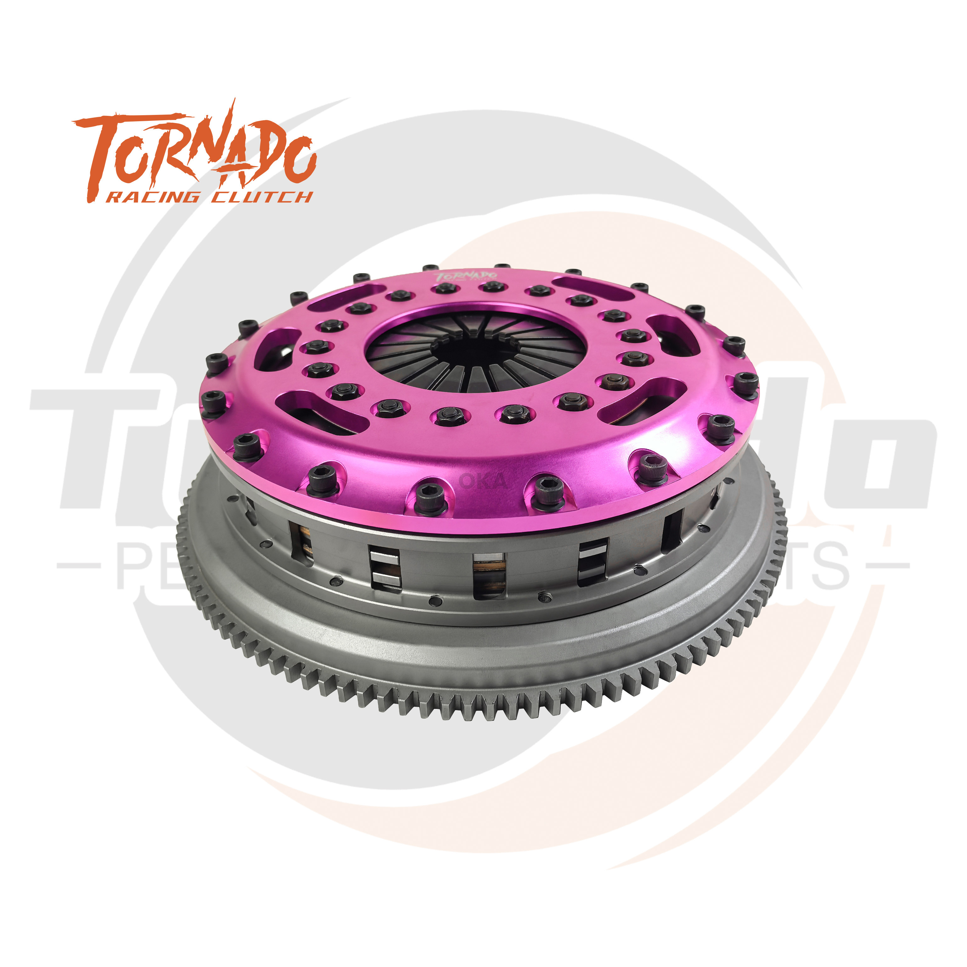
You cannot approach a multi-disc assembly with guesswork. The tooling requirements for this job are absolute. You need precision digital calipers, a high-quality micrometer, a machined straight edge, and a reliable depth gauge. We strongly advise you to avoid tape measures, standard rulers, or visual approximations. They will fail you. Calipers provide a quick overall check, but a micrometer gives you the exact thickness down to the ten-thousandth of an inch.
First, you must determine the overall assembly thickness. This involves measuring the total combined height of all friction discs and floater plates while they sit outside the vehicle. Place the components on a completely flat surface, like a granite surface plate or a thick piece of plate glass. Stack them in their exact operational order. You must compress them firmly by hand to eliminate false air gaps before measuring the total height. This number represents your master stack height.
Next, focus on establishing the baseline tolerances. You must compare the manufacturer's nominal "new" stack height against the absolute "minimum acceptable" wear limit. Every manufacturer dictates a specific wear window before a complete rebuild becomes mandatory. Operating below this minimum limit risks sudden and total clamp load failure on the track.
Standard Measurement Zones and Acceptable Tolerances Checklist
Component / Zone | Primary Tool Required | Critical Tolerance Check |
|---|---|---|
Overall Stack Height | Digital Calipers (8-inch+) | Compare measured total against nominal new height |
Friction Disc Thickness | Outside Micrometer | Check for edge taper and absolute minimum thickness |
Floater Plate Flatness | Straight Edge & Feeler Gauge | Maximum warp limit (typically fails if over 0.003") |
Flywheel Step Depth | Precision Depth Gauge | Verify exact seating depth for the pressure plate cover |
Building a reliable driveline requires a strict, repeatable measurement process. We will break down exactly what you must measure when evaluating a high-performance triple disc racing clutch kit.
Begin by measuring the thickness of each individual friction disc. Do not assume they wear evenly across the pack. The disc closest to the flywheel often sees different thermal loads than the disc closest to the pressure plate. Track each disc separately in a logbook. Next, check the intermediate floater plates for precise thickness and flatness. You must look for signs of thermal warping. Extreme heat cycles warp the steel. Warping acts as a mechanical spring, pushing the stack apart when it sits uncompressed on your bench. This creates artificially high, false stack height readings. Place a straight edge across the face of the floater plate and attempt to slide a 0.003" feeler gauge underneath it. If it slides through, the plate is warped and belongs in the trash.
You must measure the flywheel step height accurately. The step is the machined height difference between the friction mating surface and the pressure plate bolt-down surface. This ensures the pressure plate seats at the exact engineered depth. An incorrect flywheel step directly alters the clamp geometry. After you assemble the pack on the flywheel and torque the cover down, verify uniform finger height across the diaphragm spring. You want the fingers to sit perfectly level. Uneven fingers cause erratic release, pedal pulsation, and engagement shudder. If the fingers vary significantly in height, you likely have a misaligned friction disc spline or debris trapped deep in the stack.
Calculating your CSC air gap accurately prevents immediate catastrophic bearing failure. Neglecting this crucial step destroys hydraulic release bearings instantly.
Measure the Bellhousing Side: Calculate the distance from the bellhousing engine-mating surface to the release bearing face. You must push the bearing all the way back (fully compressed) to get an accurate reading. Use a straight edge across the bellhousing and measure down.
Measure the Engine Side: Calculate the distance from the engine block bellhousing-mating surface to the tips of the clutch fingers. Again, use a straight edge across the block and measure down with a depth gauge.
Calculate the Gap: Subtract the bellhousing measurement from the engine block measurement.
This math verifies your specific required air gap. The target gap typically falls between 0.100” and 0.125”, depending heavily on the specific bearing manufacturer. If your gap is too tight, the bearing rides the fingers constantly, boiling the fluid. If it is too loose, the bearing will overextend and blow out its internal seals.
Your initial kit selection directly impacts long-term serviceability. You should evaluate a multi-disc system based on its overall rebuildability. Does the manufacturer sell individual, thicker floater plates? You need these thicker plates to compensate for normal friction material wear over a season of racing. A high-quality kit offers scalable solutions to keep the stack height within spec without forcing you to buy entirely new friction discs prematurely.
We must also look at shimming considerations carefully. Assess the mechanical risks and verify manufacturer compliance before using shims behind the CSC to correct geometry. Shimming behind the hydraulic bearing corrects the air gap, but it does not fix a depleted clutch pack. Relying heavily on shims instead of rebuilding the internal clutch pack is a temporary band-aid. Eventually, rebuilding the pack with fresh friction discs and properly sized floaters is the only safe solution. Over-shimming a worn pack leaves you with dangerously low clamp load.
You must factor in the thermal expansion assumptions of your setup. A racing clutch operates under extreme track conditions. Heat changes everything inside the bellhousing. The measurements you take cold on a workbench will shift significantly under operating temperatures. The sintered iron or cerametallic friction material expands, and the steel floaters swell. If you set your cold clearances too tight, thermal expansion will cause severe drag once the engine reaches racing temperature. Always leave adequate room for this expansion by adhering strictly to the manufacturer's specified air gap range. Never assume tighter is better.
Even experienced builders make critical measurement errors when rushing an installation. Avoiding these common pitfalls ensures your transmission survives the rigors of racing.
First, beware of false readings caused by debris. Microscopic clutch dust or tiny machining burrs left between the floaters skew your caliper readings. A single speck of trapped grit can add 0.005" to your overall stack height. Always clean every single surface with high-quality brake parts cleaner and a lint-free cloth before taking any measurements. The environment must remain surgically clean.
Second, never ignore irregular wear patterns. A common mistake involves taking measurements from only the center of a friction disc. Some builders only measure the outer edge. You must take measurements at multiple points. We recommend checking four to six different locations around the circumference of each disc. This accounts for radial tapering and uneven pad wear. If a disc measures 0.250" on one side and 0.240" on the opposite side, it is severely tapered. Tapered discs dramatically reduce contact area and must be discarded.
Finally, avoid the danger of assuming perfect factory calibration. Never assume a brand-new, out-of-the-box kit is perfectly stacked. Mistakes happen during packaging, and parts get mixed up in transit. Trust the manufacturer, but verify the assembly yourself. Measure the new kit immediately to establish your baseline data. This early verification protects your investment and provides a reference point for all future wear checks.
Stack height measurement serves as your definitive final gatecheck. You must complete this verification process carefully before marrying the engine and transmission together. Doing the math correctly guarantees mechanical harmony between the hydraulic release bearing and the pressure plate diaphragm spring.
Before you finalize the build, execute these action-oriented next steps. First, log all baseline measurements of the new kit in a dedicated setup notebook so you have a future reference. Second, verify and adjust your CSC clearances to match the exact engineered air gap required by the bearing manufacturer. Third, torque all pressure plate and flywheel bolts strictly to factory specifications using a recently calibrated torque wrench. Finally, schedule your first post-break-in wear measurement after the initial test sessions to track early friction loss and ensure everything seats properly.
A: The general industry range for acceptable tolerance typically falls between +/- 0.010" and 0.020". However, you must emphasize manufacturer-specific compliance. Every brand engineers their diaphragm spring to operate within a highly specific window. Exceeding this window alters the clamp load exponentially. Always refer directly to the specification sheet provided with your specific kit to ensure safety.
A: No, you cannot mix these parameters. A triple setup has a significantly thicker total pack height and fundamentally different release travel requirements. The diaphragm spring angle behaves differently when compensating for three friction discs instead of two. Using double-disc baseline data on a triple configuration will result in either severe transmission drag or immediate slipping.
A: Warped floater plates act like a mechanical spring inside the assembly. When uncompressed on a workbench, the bowed shape pushes the friction discs apart. This falsely inflates your measured overall height. If you rely on this inflated number, you will calculate your bearing air gap incorrectly. You must identify and replace warped plates before taking final baseline measurements.
A: You must replace the discs when the total overall stack height falls below the manufacturer’s minimum specification, or when individual discs taper beyond 0.005". Once adjusting the slave cylinder air gap via shimming is no longer viable, disc replacement is mandatory. Continuing to run heavily depleted friction discs will cause sudden clamp load failure under peak torque.


